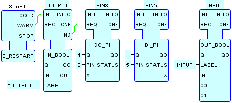


In this System Configuration:
-
Pin 3 (
GPIO02) of the Raspberry Pi 2 GPIO header is configured as an output using an instance of theDO_PItype. -
Pin 5 (
GPIO03) is configured as an input using an instance of theDI_PItype. - The output on pin 3 is connected to the input on pin 5 via a jumper wire for loopback testing.
-
Upon launching the system configuration, the following test window
is opened:

-
Clicking on the
OUTPUTcheck box causes theOUTPUT.OUTvalue to flip; this value is passed to thePIN3.Xinput. -
An event is passed from
OUTPUT.INDtoPIN3.REQ; this causes the flipped value atPIN3.Xto be written to pin 3 of the Raspberry Pi 2 GPIO header. - The output state is passed electrically from pin 3 to pin 5 of the GPIO header.
-
An event is passed from
PIN3.CNFtoPIN5.REQ, which causes the value of the input at pin 5 of the header to appear atPIN5.X, which is passed toINPUT.IN. -
An event is passed from
PIN5.CNFtoINPUT.REQ, which causes the INPUT display to be updated with the new value ofPIN5.IN.